|
Overview |
Suspension Kinematic Design Overview
|
|
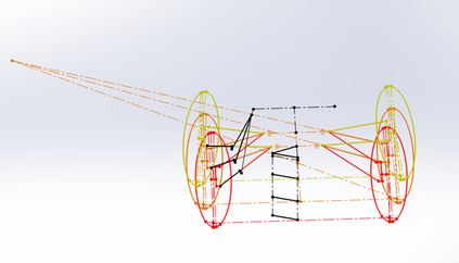
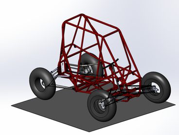
Kinematic sketch of 2016 front suspension geometry (left) and full vehicle assembly (right)
A series of sketches was created in SolidWorks which tracks the overall motion of the suspension including camber, caster, and roll center characteristics. This master sketch was used to create links and an assembly which can be moved and iterated through design studies to show the suspension and steering motion in all scenarios. Models of both suspensions and frame can be assembled to show the full vehicle response to corners and obstacles. By using pictures, videos, and sensors the motion of the roll pitch and yaw motions of the vehicle can be measured and compared to the model to ensure performance. The assembly shown in the top right holds the wheels fixed to the ground and has equations for each shock length, which can display the motion of the vehicle in every scenario. A sensor suite was designed to track the motion analytically.
|
Sample 1 |
Suspension Motion Sensor Design
|
•Problem
– Typical sensors used to measure the motion of the suspension are either unreliable or costly. •Goal – Utilize a set of rotary potentiometes to measure the motion of the suspension at each corner and on the steering column to accurately measure motion of the suspension during travel. •Solution – The system was implemented on the car during testing and run through a series of obstacles and corners. Video was taken in conjunction to help understand the output. - A matlab script was written to correlate the outputs of each potentiometer with vehicle speed. - This helped to identify the pitch/roll angles to use during geometry design and quantifies tuning changes to shocks and tires. |
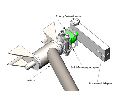
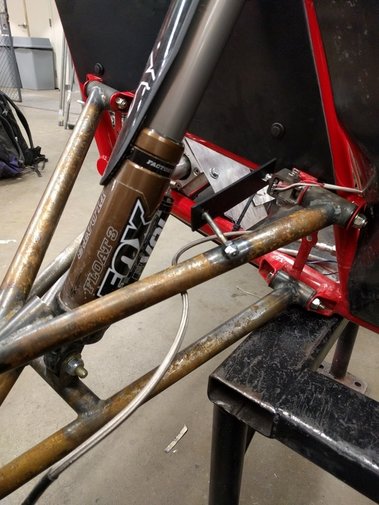
Schematic of sensor design (above) and implemented on the car (below)
|